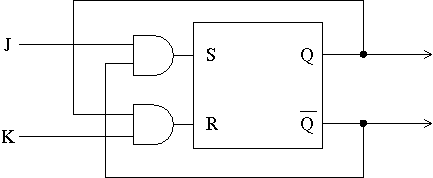
(The clock input to the JK flip-flop should be supplied directly to the internal SR flip-flop.)
Duration: 3 hours
No aids allowed
Make sure you have all 15 pages (including this page and the two appendices). (Don't panic about the page count -- there's lots of extra space for answers.)
Answer all questions. Answer questions in the space provided. Answers not in the correct space will not be graded unless a note in the correct space says "see page ..." and the answer on that page is clearly labelled with the question number.
Be careful not to get stuck on some questions to the complete exclusion of others. The amount of marks or answer-space allotted does not indicate how long it will take you to complete the question, nor does the size of the answer-space indicate the size of the correct answer.
Exam solutions will be made available on the course web page in a few days.
Do not open this booklet until you are instructed to.
1. [6 marks]
a) Using only AND, OR, XOR, and NOT gates, draw a "half-adder".
(A half-adder adds two one-bit numbers to produce a one-bit result and a
carry-out. There is no carry-in.)
b) Using only two half-adders and an OR gate, draw a "full adder". (A full-adder adds two one-bit numbers plus a carry-in, producing a one-bit result and a carry-out.)
c) Using four full-adders and any other needed individual gates, draw a circuit which adds the constant three (0011) to a four-bit input number.
2. [6 marks]
Recall how we made a JK flip-flop out of a master-slave SR flip-flop:

(The clock input to the JK flip-flop should be supplied directly to the
internal SR flip-flop.)
a) Draw a JK flip-flop with synchronous reset: If the synchronous reset input is 1 when the clock goes from 1 to 0, the Q output will be 0 for the next cycle regardless of the values of J and K.
b) Draw a JK flip-flop with asynchronous reset: When the asynchronous reset input is 1, the Q output immediately becomes zero regardless of the clock state.
3. [6 marks]
a) Draw a "counter" which counts in the sequence 3, 2, 1, 3, 2, 1, ... .
b) Draw a "counter" which counts in the sequence 3, 2, 3, 2, ... .
4. [5 marks]
Design a circuit with two inputs: Clock and X. X is sampled on each clock
cycle. The output Z is 1 if and only if the most recent three X samples were
0, 1, and 1, in that order.
Optional hint: One way of doing it involves a three-bit shift register.
5. [15 marks]
Here are all pairs of condition codes. For each, give an example four-bit
addition which will result in these two condition codes being set to 1 (the
other two might be set or cleared). However, one of the pairs is impossible,
which you should also identify and explain in a sentence why it is impossible.
The first one is completed as an example.
C V:
          1011
        + 1011
          ----
          0110
(a) C N:
(b) C Z:
(c) V N:
(d) V Z:
(e) N Z:
6. [10 marks]
Here is a program fragment to compute the greatest common divisor of x and
y, using Euclid's algorithm.
Here it is in Python:
        while y != 0:
            t = x
            x = y
            y = t % y
Here it is in C or Java:
        while (y) {
            int t;
            t = x;
            x = y;
            y = t % y;
        }
(I think that everyone here knows Python, C, or Java. If not, please ask me
to write this code out for you in some other high-level language
you know.)
Write VELMA code (not a subroutine: nothing is on the stack, you can use any registers) which is equivalent to the above. Assume that x is in R0 and y is in R1 before your program fragment is executed.
7. [16 marks (in four parts)]
a) Earlier models of the PDP-11 did not have multiply and divide instructions.
Write a VELMA subroutine which takes two parameters and multiplies them
by repeated addition, without using MUL. Assume that the two numbers are
non-negative (although either or both of them might be zero). For example,
if your subroutine is called with parameters 4 and 7, it would compute
4+4+4+4+4+4+4. Don't worry about overflow.
b) Write another VELMA subroutine which uses the above subroutine to multiply two arbitrary integers. It calls your part (a) subroutine with the absolute values of the two parameters. Then, if appropriate it arithmetically-negates the result so as to return the correct product of the original two integers. To compute "-x" you may use the PDP-11 "NEG" instruction which arithmetically negates its single operand in place; e.g. "NEG R1" does R1 <- -R1. Don't worry about overflow. Remember that "SUB R0, R1" performs R1 <- R1 - R0.
c) Write a main program which uses your part (b) subroutine to compute x-y*z+a*b, where x is a memory location identified by the label X, and y, z, a, and b are registers R2, R3, R4, and R5, respectively.
d) Why did I have to say "don't worry about overflow" in part (b) above? That is, what parameters would cause your subroutine in part (b) to overflow even though the subroutine in part (a) does not overflow when it's called? (Give an example pair of parameters which has this property and explain where the overflow occurs.)
8. [10 marks]
Our standard fetch sequence looks like this:
0. PCout, MARin, Read, Zero A, Set Carry-In, Add, ZinExplain the following elements of step 0 at a high level -- state the purpose of the operations.
1. Zout, PCin, Wait MFC
2. MDRout, IRin
a) What is the purpose of PCout, MARin, Read? (Why is it appropriate to do this?)
b) What is being added? How does step 0 above cause this addition? Why do we want to add those things?
9. [6 marks]
a) Write microcode to perform a VELMA "JUMP" instruction (the target is in
the "mem" field, which is available as AddressFieldOfIRout).
(Start at step 3, after the standard fetch sequence.)
b) Write microcode to perform a VELMA "JUMP@" instruction (e.g. "JUMP @1234").
10. [10 marks]
Suppose a RISC CPU instruction set with a delayed branch rule and with the
three-register instruction format.
Write code for such a RISC CPU which
adds the integers from 1 to 1000.
State in which register we can find the sum when your program HALTs.
11. [10 marks]
Consider,
where x = 0 through 7 inclusive,
the values of the sum from 0 to x inclusive, as two-digit decimal numbers.
They are, sequentially (in base ten):
00, 01, 03, 06, 10, 15, 21, and 28.
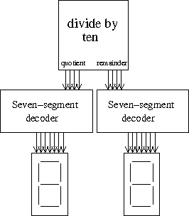
Draw a circuit which produces a display (using two seven-segment digit displays) which goes through the above sequence repeatedly, i.e. 00 comes after 28. Note that this means that other than when x=0, each output adds to the previous output.
You can use any standard high-level components which we've used in the course, such as registers and adders. (And obviously you will use two seven-segment decoders, as provided below.)
[then there was a big space, with the lower-right corner containing:]

End of exam. Total marks: 100. Total pages: 15 including appendices.