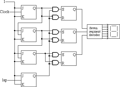
The strategy used here is to construct D latches explicitly out of SR latches so that I can get into the middle of them and AND both of the SR inputs with the "lap" value. Thus when the "lap" value is zero, no changes will happen to the SR latches. But when the lap value is 1, they will basically just be a wire, the signal will pass right through.
You might prefer the above circuit to have an inverter (NOT gate) between the lap's JK flip-flop's output and everything it goes to. To draw it as I did inverts the meaning of the output of the lap JK flip-flop -- instead of 1 meaning that the lap button is enabled, it means that it is disabled. But in fact, the user of this circuit would not be able to tell this without a logic probe, thus it is a purely internal matter.